Stephenson and Edwards – 1844

Stephenson and Edwards Patent 3546 Lock 
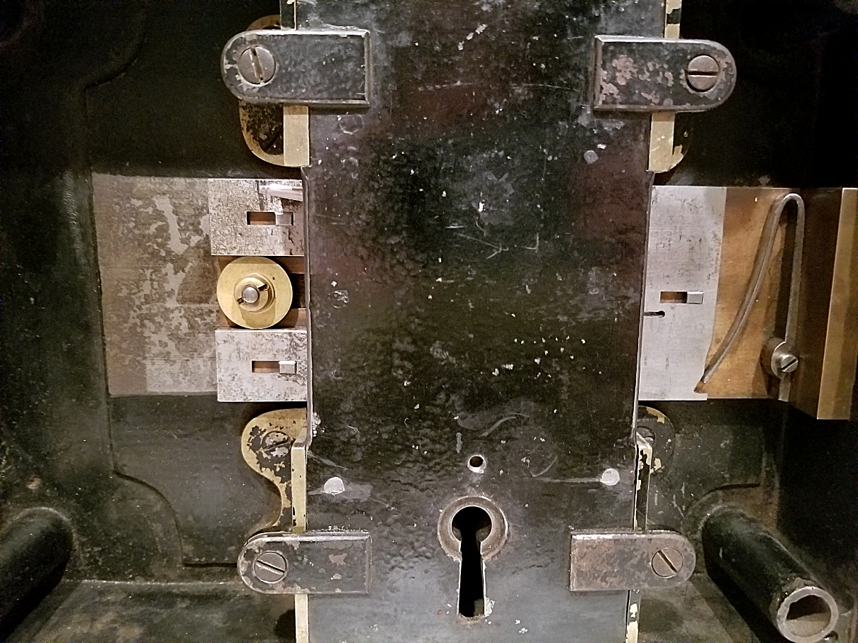
Stephenson and Edwards Patent 3546 Lock Internals

A similar article to this was first published in the WCLCA Journal The Antique Lock Collector in the July-September 2018 edition.
This lock comprises two patents, both by Marcus Stephenson and Oliver Edwards of Boston. Both patents date to April 17, 1844. It was manufactured by Edwards, Holman, and Fernald (commonly known as Edwards and Holman). Patent 3543 describes the locking mechanism while patent 3546 describes the detector mechanism. Leading with a fantastic summary of the lock from a published testimony:
“It embraces the celebrated Combination and Permutation principles, with the wonderful Detector Safeguard, which is so constructed, that should a burglar introduce an instrument to remove the bolt, he would redouble its security, or in other words, it would require two keys, each susceptible of a vast number of changes, to unlock it, thus putting it entirely out of his power to open it, were the keys in his possession. We have never known a lock of this kind to be forced or picked, and we believe it an impossibility for even the most adroit picklock to overcome it.” — Willis & Co. February 9, 18441
1Edwards, Fernald & Co. Catalog, Trade Literature Collection, National Museum of American History Library, Smithsonian Libraries, Washington D.C., 21-5-2018
The image below is of the original key. It features a style very similar to the more common Solomon Andrews changeable bit keys. In this key, the end piece that unscrews is just the small endcap, while in the Solomon Andrews key it is the entire piece in front of the main bolt-acting bit. Each of the bits comes off of the key once the endcap is unscrewed and can be re-organized to be re-keyed to the lock if desired by changing the levers’ order inside the lock. Each of the bits is individually numbered. On this particular key, they are numbered from one to twelve, from shortest to longest, although they are not always numbered in length order as will be seen later. The shaft is square with a threaded hollow end for the endcap to be screwed on to.

Stephenson and Edwards Patent 3546 Key 
Stephenson and Edwards Patent 3546 Key Apart

The outer case of the lock can be seen in the first image above. Once the screw in each corner and the one in the center are removed, the face plate can be taken off to reveal the internals. Another plate blocks the view of the individual levers, but some of the unique workings can be seen. As the key is turned to lock the lock, the levers shift and the bolt is thrown. Now, the unique detector mechanism comes into play. When someone tries to gain access to the lock either through the use of a false key or maliciously attempting to pick it, a mechanism is tripped. Once tripped, the lock will no longer unlock, even with the correct key. Either a second key has to be used (as designed) or the bits on the key have to be re-arranged until they are in alignment with the reset combination which allows the detector mechanism to reset, thus re-activating the lock. With the bits in the correct position to reset it, the key is turned as if locking it, and the bolt shifts all the way back into the locked position and is reset. Note: the detector mechanism is not shown in these photos.

Stephenson and Edwards Patent 3546 Detector Closeup 
Stephenson and Edwards Patent 3546 Detector Reset Closeup


The left image above shows the lock in its locked state from the left side. Note the little openings in each of the levers. In order to reset the lock after a malicious attempt, the key needs to be re-arranged to allow the bar seen in the photo to pass through them and reset the mechanism. This right image shows the lock in motion while being reset. Note the bar passing through the levers.

Stephenson and Edwards Patent 3546 Internals with Top Plate Removed

Once the middle plate is unscrewed, each of the levers can be seen. They are held in place left to right by the two vertical plates on either side and are held in back to front by the plate hence removed. Assisting in applying vertical pressure is a spring on each lever that is placed around a rod near the top of the lock. Each spring is separated by a small washer. The lock is shown here in its unlocked state. As the lock is locked, the key acts on the bottom portion which lifts the levers in their entirety and when lifted to the right height allows the passage of the metal bar through the gap seen in each lever. You can see the metal bar in the middle of the image in the left opening of the levers.

Each of the levers is individually numbered, corresponding to the numbers on the bit for the locking code. This unique lock was built with the utmost degree of care and craftsmanship. The detector mechanism is ingenious, and the lock itself represents an engineering marvel. It weighs in at about 27 pounds and measures approximately 12.25 x 9 x 2.25 inches.

Bolt markings showing
O. Edwards
E. Holman
Patent
Boston

Edwards Holman T Handle Key 
Edwards Holman T Handle Key Apart

Here is another example of an Edwards and Holman key. The T-handle on the top unscrews, but it has an indention in the threads like it was intended to be affixed. I believe the T-handle is either original to the key or an in-faith old replacement as I have seen another T-handle example (with a slightly different appearance), and their later patent from 1852, patent 9126, shows a T-handle key. This particular key is very similar to the previously shown one, except it has 14 bits, a slightly larger end screw, and different materials of construction. In this particular example, the bits are not numbered in length order.